Electromagnetism
Matthew Williams
||8 min readAC GeneratorCSEC PhysicsDC MotorElectromagnetismFleming's RulesInduced EMFPaper 01Paper 02Section DTransformer
Magnetic fields around conductors and solenoids, the right-hand grip rule, the relay, force on a current-carrying conductor, Fleming's left-hand rule, the DC motor, electromagnetic induction, the AC generator, and the transformer (turns ratio, efficiency).
Magnetic Field Around a Current-Carrying Conductor
An electric current produces a magnetic field around the conductor. The shape of the field depends on the conductor geometry.
Straight wire: concentric circles around the wire. The direction follows the right-hand grip rule, point the right thumb in the direction of conventional current; the fingers curl in the direction of the magnetic field.
Flat coil: field lines pass through the centre of the coil perpendicularly.
Solenoid (coil of many turns): the field inside resembles a bar magnet with a strong, nearly uniform field along the axis. The end from which field lines emerge acts as the north pole.
Relay
A relay uses a small current in an electromagnet to switch a separate circuit carrying a large current. When the control current flows, the iron core is magnetised and attracts a soft-iron armature, which closes (or opens) contacts in the main circuit. Used in car starters, security systems, and industrial control.
Force on a Current-Carrying Conductor
A conductor carrying current in a magnetic field experiences a force (the motor effect). The magnitude of the force depends on the current, the length of conductor in the field, and the strength of the field.
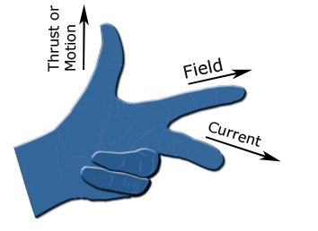
Fleming's left-hand rule (motor effect — force on a current in a field) gives the direction of the force:
- First finger → direction of the magnetic Field (N to S).
- seCond finger → direction of conventional Current.
- Thumb → direction of the Thrust (force on the conductor).
The DC Motor
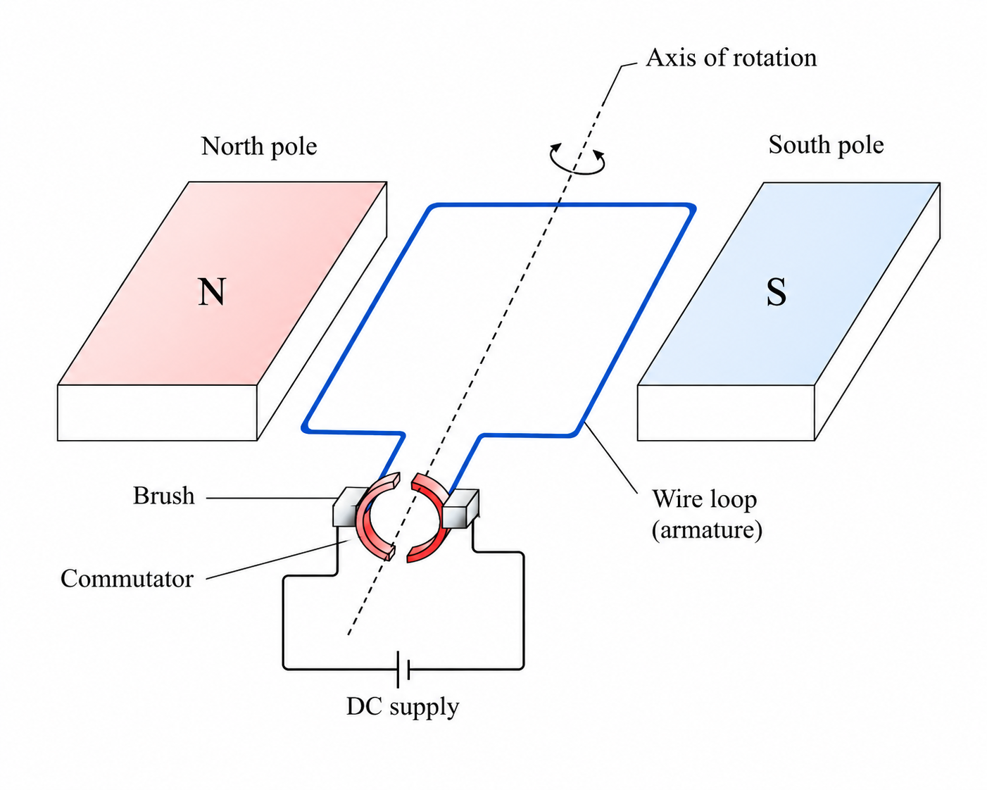
A DC motor uses the force on a current-carrying conductor in a magnetic field to produce rotation:
- Current flows through a rectangular coil placed between the poles of a magnet.
- The motor effect produces forces on opposite sides of the coil in opposite directions, creating a turning couple.
- The coil rotates until it is perpendicular to the field.
- A split-ring commutator reverses the current direction every half turn, so the forces continue to drive rotation in the same direction.
- Carbon brushes maintain electrical contact with the commutator as it rotates.
Increasing the current, using more turns on the coil, or using a stronger magnet increases the speed or torque of the motor.
ExampleDirection of force on a motor coil (2021 Paper 02, Q5)
A rectangular coil ABCD is placed between the poles of a magnet with the N pole on the left and S pole on the right. Current flows through the coil in the direction A to B to C to D to A. In side DA, the current flows toward the viewer (out of the page).
State the direction in which side DA moves.
Apply Fleming's left-hand rule:
- First finger (Field): The magnetic field points from the N pole to the S pole — from left to right.
- Second finger (Current): In side DA, the current flows toward the viewer — out of the page.
- Thumb (Thrust): Points upward.
Side DA moves upward.
Side BC carries current in the opposite direction (into the page), so the force on BC acts downward. The two forces on opposite sides form a couple that rotates the coil.
Electromagnetic Induction
When the magnetic flux through a conductor changes, an EMF is induced in it. This is Faraday's Law. If the conductor is part of a closed circuit, a current flows.
Factors that increase the induced EMF:
- Moving the magnet (or coil) faster.
- Using a stronger magnet.
- Increasing the number of turns in the coil.
Lenz's Law: the induced current flows in a direction that opposes the change causing it (it obeys conservation of energy).
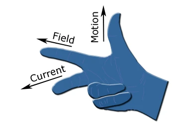
Fleming's right-hand rule (generator effect — induced current from motion in a field) gives the direction of the induced current when a conductor moves through a magnetic field:
- First finger → direction of the magnetic Field (N to S).
- Thumb → direction of Motion of the conductor.
- Second finger → direction of the induced Current.
The AC Generator
An AC generator rotates a coil in a magnetic field to produce alternating EMF:
- As the coil turns, it cuts through field lines, an EMF is induced.
- The EMF is maximum when the coil is parallel to the field (fastest rate of cutting) and zero when the coil is perpendicular to the field.
- As the coil turns past zero, the cutting direction reverses, so the EMF reverses, this produces the sinusoidal AC output.
- Slip rings and brushes maintain continuous electrical contact as the coil rotates.
Increasing rotation speed increases the frequency and the peak EMF.
Transformers
A transformer changes the voltage of an AC supply. It consists of two coils (primary and secondary) wound on a shared iron core.
where , are the primary and secondary voltages, and , are the number of turns.
For an ideal (100% efficient) transformer, power input equals power output:
Step-up transformer: , voltage increases, current decreases.
Step-down transformer: , voltage decreases, current increases.
Why AC is Used for Power Transmission
Power is transmitted at very high voltage (and correspondingly low current) to minimise energy lost as heat in the cables (). Transformers can only work with AC, a DC supply through a transformer produces a constant flux, inducing no EMF.
ExampleTransformer calculation (2018 Paper 02, Q6)
A transformer has turns and turns. Primary voltage V, primary current A.
Input power:
Secondary voltage:
This is a step-up transformer (secondary voltage much greater than primary).
Maximum secondary current (100% efficiency):
Exam Tip
For the transformer ratio, write and identify which is the primary and which is the secondary before substituting. The side connected to the supply is the primary; the load is on the secondary.
Fleming's left-hand rule applies to the motor effect (force on a current in a field). Fleming's right-hand rule applies to the generator effect (induced current from motion in a field). Remember: Left = Motor, Right = Generator.